
WSPR-RX V1 Documentation page
Tel. 123-456-7890
Fax. 123-456-7890
500 Terry Francois Street,
San Francisco, CA 94158

Schema
Source code

WSPR-RX Hardware version 1 is a fixed frequency receiver with the following characteristics:
-
Built for one fixed frequency for one of the radio amateur bands .
-
Is designed to be "plug-and-play" with zero settings.
-
Powered from a USB port from a computer or using a USB charger.
-
Intended to be used with a computer running a WSPR reception software.
Data:
-
Frequency:
Dependent on model.
17m model= 18.104,600MHz
20m model= 14.095,600MHz
30m model= 10.138,700MHz
40m model= 7.038,600MHz
80m model= 3.568,600MHz
160m model= 1.836,600MHz
630m model= 474.200kHz
2190m model= 136.000kHz -
Sensitivity:
-117dBm or better (3dB SN/N in 500Hz Bandwith) -
Size:
100x70x25mm. -
Power usage:
0.3W -
Weight:
160g
Theory of operation:
The WSPR-RX V1 is a direct conversion receiver that receives on one fixed frequency on a Ham band.
When connected to computer that runs a WSPR software it will form a system for trouble free WSPR reception on a single band.
Internally it uses a PLL controlled local oscillator (LO) that can be tuned to any frequency from 8kHz to 150MHz.
The LO is controlled from an Arduino that determines the frequency at start up.
The LO is feeding a mixer that mixes the incoming radio frequency (RF) from the antenna with the LO.
The output is a low frequency (LF) output that is amplified and low pass filtered by the LF amplifier.
The LF signal is output on the 3.5mm audio connector.
The RF signal is filtered out using a double tuned bandpass filter that select the signals of interest.
This bandpass filter is factory tuned to the WSPR frequency.
The band pass filter can only be tuned over a narrow range and there are therefore different models sold that has different bandpass filters fitted.
Operation.
To operate the WSPR-RX V2 do the following:
Connect it to a computer:
-
Connect the "Audio Out" from the receiver to a line-in or microphone input on a computer using an appropriate audio cable.
-
Connect an HF antenna to the SMA connector marked "Antenna Input".
-
Connect a 5V power source to the micro USB connector.

Configure the computer software
-
Start the appropriate WSPR receive software on the computer, e.g on a Windows based PC you may use the software "WSJT-X".
-
Configure the software to use the correct soundcard and adjust the volume using the windows sound mixer adjustment.
-
Select the appropriate Ham band and if you intend to send your report to the WSPR network make sure to enter you Ham radio call sign and position in the settings as well.
-
Tick the "Upload spots" option.
-
Done!
The receiver is designed to be maintenance free and "plug-and-play" so there are no settings or adjustments that needs to be done on it.
Once the computer program have ben properly set there is nothing to adjust.
The receiver will always be on frequency and should hopefully give many years of trouble free operation.
Service.
The Receiver Frequency is calibrated and trimmed at delivery but if the user wants to re-calibrate or change the LO frequency, the following procedures can be used.
Setting what Ham band is received.
Note that the bandpass filter is manufactured for one single band so the receive band can not be changed without replacing and readjusting the bandpass filter.
The jumper JS1 to JS4 sets the band.
The Jumpers JS1- 4 to 1 are located close to the Arduino Reset button on the PCB.
Picture indicates with a red square the frequency jumpers.

In version 0.43 of the firmware the frequency table was the following (Might be subject to change in later firmware versions).
Frequency Calibration and Bandpass adjust assist mode.
The Receiver Frequency is calibrated and trimmed at delivery but if the user wants to reaffirm or change it the following procedure can be used:
Set the Sliding Switch "S1" to the "Trim" postion.
S1 is located next to the Antenna SMA connector.
Picture shows what way to move the slider.

Push the Reset button on the Arduino or remove and reapply power to the receiver.
The receiver start up sequence will detect position of S1 and enter Trim mode.
The Trim mode has three modes that it will enter in sequence.
Every time the SW3 button (marked Enter) is pushed the Trim mode will advance one step to the next mode.
The modes are in order:
-
Course frequency adjust.
-
Fine frequency adjust.
-
Bandpass adjust assist.
Course frequency adjust:
When the receiver first enters trim mode the trim indicator D3 will light up red and stay lit.
The LO is now programmed to output exactly 10MHz regardless of the Jumper settings.
To calibrate the crystal frequency of the WSPR-RX the user needs to measure the LO frequency at test point TP3 with a high resolution frequency counter that have a good frequency reference or alternatively use an Oscilloscope that have a 10MHz frequency standard on another channel for comparison.
Picture shows using a frequency counter to measure the 10MHz signal.

Use the Calibration buttons SW1 and SW2 marked + and - on the PCB to increase or decrease the LO frequency in course steps, every click on the + or - button will adjust the crystal frequency with 100Hz up or down for every click.
As the crystal is usually at 26MHz this corresponds to a change in the 10MHz LO of less than 50Hz for every click.
Once the closest match has been found and the LO is less than 50Hz away from true 10MHz then press Switch SW3 marked "Enter" on the PCB.
Fine frequency adjust:
At the press of the Enter button the trim indicator D3 will briefly go out and then light up again as an indication that fine frequency adjust trim mode has been entered.
In this mode the crystal frequency changes 1Hz for every plus or minus click with SW1 or SW2
This will affect the 10MHz output on the LO Testpoint TP3 with less than 0.5Hz for every click.
Keep adjusting the Frequency with the plus and minus buttons until the LO is as close to true 10MHz as possible.
When the LO output is as close to 10MHz that can be had then once more press the switch SW3 marked "Enter"
The red LED D3 will now start flashing rapidly and the LO freqency will change from 10MHz to the receiver frequency as chosen by the jumpers J1.
At this point the Frequency calibration is completed and the flashing D3 indicates that the receiver is now in bandpass adjust assist mode.
Note: The Frequency adjust procedure dosen't actually change the crystal oscillator frequency but instead determines the exact frequency it is oscillating on.
This is saved in the Arduino EEPROM when the Arduino goes in to bandpass adjust assist mode and will be used at subsequent boot-ups that follows.
The frequency data for the crystal oscillator will be used by the PLL calculations.
Being able to know exactly what frequency the crystal oscillator is oscillating on ensures that the calculations are correct and thus the PLL output frequency will be correct.
Bandpass adjust assist.
The last stage of the trim mode is the bandpass adjust assist mode and in this mode the LO is set to the correct frequency and a second output of the PLL is activated and set to frequency that is 1500Hz higher up in the middle of the receive pass-band.
This second signal is greatly attenuated to bring it down to levels that can be feed in to the receiver.
The signal is routed to the antenna input by the Trim switch and will pass trough the bandpass filter and being down-mixed by the mixer and will result in a audio tone of 1500Hz at the audio output.
By listening on the audio output or by observing test point TP4 with an oscilloscope the bandpass filters can now be peaked by adjusting the trim capacitors C1 and C6.
Picture indicates with red squares the bandpass trimmers C1 and C6.
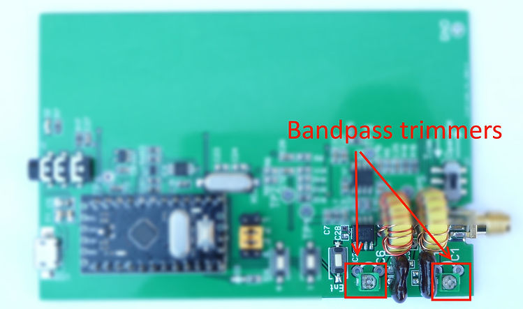
Start by trimming C1 until maximum signal and then move over to C6, go back to C1 and do fine adjustments and finish of with C6 again.
A small note on the timmers:
C1 and C6 is one of two types of Murata trim capacitor and they both have some quirks to them.
-
The one pictured in the photo is a green plastic type that has a transparent film on the top.
This film on top can make it difficult to adjust the trimmer and some downward force will be needed by the trim tool to make contact. This is normal and the transparent film is there to protect the inside of the trimmer from any washing stage in the PCB production. -
The other type is a metal type, this dosen't have a protective film but is instead sensitive to downward force of the trim tool used so on this type you should avoid using downward force and try instead to trim it with a very light touch of your trim tool. Also after adjustment, some additional settling time of a few seconds can be needed to let it settle as the capacitance seems to be pressure-sensitiv and it takes a second or so for it to settle down after adjustment.
Both of these Murata types are really good trimmers with high Q so their quirkiness needs to be accepted in the interest of high performance.
I have tried using cheap trimmers but they completely destroyed the high Q of the bandpass filter and drastically lowered the sensitivity and selectivity of the receiver so I decided to spend a few extra dollar on good quality Murata capcitors for all receiver models.
Note: The Bandpass adjust assist mode has been removed from hardware and firmware after version 0.41 for a number of reasons.
It is not recommended that the user adjust the trimmers as they will have been optimally adjusted by me using a VNA connected to the receiver input and the trimmers are not likely to change over time.
When I designed the receiver I thought it was a good idea to include the Bandpass adjust assists as users without access to a signal generator would be able to tune the Bandpass filters.
But I found out it ads a lots a components to the design and as I am hand assembling the receivers it adds to the build time.
But more critically it forces me to use a certain Arduino library and that in turns grow the compiled size so that it can not fit in to an Arduino using an Atmega168 that I want to use for cost and supply reasons.
So the later firmware version removes the code and the latest revisions of the hardware version 1 don't have the required components populated on the PCB for the assist mode to work.
The earlier versions of the firmware that have this feature is uploaded on Github so users that want to experiment with it for their own designs can check it out.
After the calibration is complete the user will end Trim mode by moving the slider S1 to the "Operate" position.
The Trim indicator D3 will turn of and the Receiver will go back to normal operation.
Changing the firmware.
With a serial adapter the Arduino can be reprogrammed from the Arduino IDE.
This can be useful in a number of situations, for instance if you want to set the receiver to a different frequency than the predefined WSPR frequencies.
Connecting to the Arduino using a USB to Serial converter.
If the you want to upload a different version of the firmware you need to connect a Serial to USB converter to the Arduino.
In the picture below the Arduino has a black connector but that is usually not populated.
Se picture for example hock-up, some designs of the Serial adapter might have to be turned up-side-down to have the correct pin-out. (The serial adapter is the Red PCB to the left in the Picture)

Once the serial adapter is in position the Arduino can be reprogrammed from the Arduino IDE.
The existing firmware displays it version number at startup and other information that can be useful.
If you want to use a Terminal software instead of the Arduino IDE set it to use 57600 as baud-rate and 8N1 for settings.
Here is an example output from a terminal software when the WSPR-RX boots:
Zachtek HF WSPR DC RX, Software version: 0.43
Initializing..
Turning on 3.0V Voltage Regulator
Frequency Jumper is set to 5 so setting receiver frequency to: 10.138,700MHz
Here is another example when the WSPR-RX goes in to Trim mode at startup:
Zachtek HF WSPR DC RX, Software version: 0.43
Initializing..
Turning on 3.0V Voltage Regulator
Frequency Jumper is set to 5 so setting receiver frequency to: 10.138,700MHz
Entering Trim mode
LO set to 10MHz, Measure at TestPoint 2 and use + and - buttons to change PLL Crystal Frequency in 100Hz steps
When done press Enter to do fine adjustment
Enter Button Pressed first time
Fine adjust, use + and - buttons to adjust Frequency in 1Hz steps
When done press Enter to save and go to bandpass trim routine
Enter Button Pressed second time
Crystal Frequency Saved
Exit trim routine by moving the Trim swith to 'Operate'
590
590
590
590
589
189
589
589
...
snip
...
516
518
513
521
527
521
153
Trim switch set to "Operate"
Exiting Trim mode
The numbers indicate the strength of the signal as it comes out from the LF amp.
This is digitized by the Arduino ADC and displayed, stronger signal equals higher value. One would trim the bandpass filters for maximum value using a trim tool and adjusting C1 and C6.
The Arduino IDE also has a "Serial Plotter" that can be used to show it as a graf during adjustments.
Changing the receive frequency.
If one wants to change the receive frequency it be done using the following procedure:
-
Connect a Serial to USB converter as outlined earlier and connect to a PC or Mac that has the Arduino IDE installed.
-
Download the latest firmware from Github and open it in the IDE.
-
In the Arduino IDE, use the "Tools" menu, submenu "Board:"and choose the board "Arduino Pro or Pro Mini"
-
Check what type of Arduino is on board, both ATMega 328 and ATMega168 has been used by me. You determine this by looking att the Arduino IC
Use the "Tools" menu, submenu "Processor:" and set it to either 328 or 168 - 5V -
Edit the source code and enter your desired frequency. The frequency is set by one of several #define statement in the beginning of the code.
#define RXFREQ23cm 25930000000ULL //23cm 1296.500,000MHz
#define RXFREQ70cm 14410000000ULL //70cm 432.300,000MHz
#define RXFREQ2m 14448900000ULL //2m 144.489,000MHz
#define RXFREQ4m 7009100000ULL //4m 70.091,000MHz
#define RXFREQ6m 5029300000ULL //6m 50.294,500MHz
#define RXFREQ10m 2812460000ULL //10m 28.124,600MHz
#define RXFREQ12m 2492460000ULL //12m 24.924,600MHz
#define RXFREQ15m 2109460000ULL //15m 21.094.600MHz
#define RXFREQ17m 1810460000ULL //17m 18.104,600MHz
#define RXFREQ20m 1409560000ULL //20m 14.095,600MHz
#define RXFREQ30m 1013870000ULL //30m 10.138,700MHz
#define RXFREQ40m 703860000ULL //40m 7.038,600MHz
#define RXFREQ80m 356860000ULL //80m 3.568,600MHz
#define RXFREQ160m 183660000ULL //160m 1.836,600MHz
#define RXFREQ630m 47420000ULL //630m 474.200kHz
#define RXFREQ2190m 13600000ULL //2190m 136.000kHz
Which one of these defines that are being used is set by the Jumper JS1 positions on the circuit board as described earlier.
If for example you have the 20m version of the receiver you will change the RXFREQ20m define.
The Frequency is entered in centiHertz, e.g if you want to use 14.100MHz you would write it as 1410000000.The ULL at the end means "Unsigned Long Long" and helps the compiler to avoid lowering the precision of the stored value.
The local oscillator will use this exact frequency and as the receiver is a direct conversion type it will receive both the lower and upper side-band on this frequency. -
Modify the Procedure void SetStartFreq() in the source code.
Find the correct case statement and modify the printout of the frequency value.
As an example if you modified the RXFREQ20m in step 5 to be 14.1MHz you would modify case statement 6 to read:
case 6:
MyFrequency0 = RXFREQ20m;
Serial.println (F("14.100,000MHz"));
break -
Recompile and upload the modified source code to the on-board Arduino.
-
Power up the receiver and using a frequency counter check the LO frequency on Test point 3
-
If you moved the frequency far from the last receive frequency you might need to adjust the bandpass filters. Use the procedure outlined earlier.
The bandpass filter has a bandwidth of 2% of the receive frequency so as a rule of thumb if you moved the receive frequency more than 1% you will have to readjust the bandpass filters.
Continuing with the 14,1Mhz as an example 1% of 14,1MHz is 141kHz.