
WSPR-TX_LP1 Version1 Documentation page
Tel. 123-456-7890
Fax. 123-456-7890
500 Terry Francois Street,
San Francisco, CA 94158


WSPR-TX_LP1 V1 is a standalone WSPR transmitter with a built in GPS module and external GPS antenna.
It has the the following characteristics:
-
Standalone operation, no PC required for operation.
-
Works on any Ham band from 136kHz to 70MHz
-
Is powered from 5V.
-
Pre-built and tested except for the low-pass filter that needs to be built by the user.
-
Has a built in GPS that is used for timing and position calculations.
-
Has a built in Arduino that runs open source software.
-
Designed to be easy to use and easy to expand
-
Powered on a USB connector with 5V.
-
Intended to be used standalone with no need for a computer once initial configuration has been done.
Data:
-
Frequency:
136kHz to 70MHz, built for one frequency as set by output low pass filter. -
Power output:
0.3Watts in 50ohm, se power table below. -
Size:
100x66x20mm. -
Power usage:
1.25W (5V 100mA at idle, 250mA at transmit) -
Weight:
40g
Theory of operation.
The WSPR-TX_LP1 V1 is low power transmitter with Arduino firmware that encodes WSPR packets and transmits them using a Silicon Labs Si5351 PLL. The output from the PLL is a square wave that is amplified by a 74AC244 Line driver IC and matched to 50 ohm by a MiniCircuits wide-band transformer.
The Reference clock for the PLL is an Abracon ASTX-H11 TCXO oscillator on 25 or 26MHz.
The reference has a 2.5ppm stability specification that ensures good frequency stabilization when transmitting the narrow band WSPR packets.
The signal exits the power amplifier as a square wave and needs to be filtered to remove overtones.
This can be done either with an external low pass filters or by populating the space on the PCB for the single on-board low pass filter.
The circuit board have an expansion header that can be used for experimentation with the optional Mezzanine Experimenters kit.
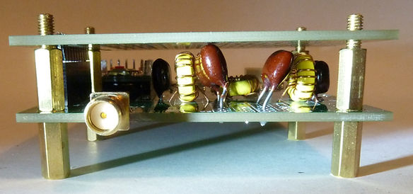
Different building blocks of the transmitter. Picture shows an early revision.
In later revisions the Arduino Pro Mini is replaced with an equivalent surface mount ATMega328P-AU

Operation.
To operate the WSPR-TX_LP1 do the following:
-
Connect the included GPS antenna to the SMA connector marked "GPS Antenna" and place the GPS puck so that is has visibility of the sky.
-
Connect an HF antenna or dummy load to the SMA connector marked "RF Out".
-
Connect a 5V power source.
The WSPR-TX_LP1 is working autonomously when it has power and no interaction is needed.
It will continuously transmits WSPR type 1 messages with the position and timing data generated by the GPS once it has received a GPS fix.
Between WSPR transmissions It will pause for some set time. It will continue to do this transmission - pause, transmission - pause, indefinitely (or at least until the power is lost).
The user can observe it's operation either by looking at the LEDs or by viewing the status messages on the serial port.
Status information from the LEDs
To monitor the operation of the device observe the yellow status LED. It will flash once every second when it is waiting for the initial GPS fix. Depending on GPS antenna position and other factors this can take just a few seconds to several minutes . Once the GPS have gotten a fix the status LED will start to double-blink every second. This is indication that the transmitter is preparing itself to send a WSPR packet, it is now waiting for top of minute on the next even minute.
Once the the transmission start the yellow status indicator will be continuously lit.
The Red TX LED will also be lit during the transmission.
Note: if the yellow status led is lit continuously indicating a WSPR transmission cycle but the Red TX LED remains off then transmission might be disabled in software, the most likely reason for this is that the call sign is not configured.
Once the WSPR packet has been sent the software will pause for some time , during this time the Status LED will be off.
When the pause is completed it will again prepare for a new WSPR transmission and the Status LED will start to double-blink every second.
Status information from the USB port.
The current status of the transmitter can be viewed on the USB port using serial terminal software.
Connect to the Serial port using the speed of 9600 Baud and 8N1 settings.
Hardware:
The hardware can be divided in to the following blocks:
Powersupply
There are two power supplies in the transmitter, 5V and 3.3V
5V:
The transmitter is powered by an external 5V supply using a micro-USB connector.
The maximum current usage by the transmitter is around 250mA.
The only electronics that use the 5V on board is the power amplifier and the 3.3V regulator. the 5V is available on the expansion port, see below for more information on the expansion port.
Before the 5V goes to any electronics it is passed though a poly-fuse that protects the external power supply in case of a short circuit on the board
The polyfuse F1 trips at 1.5 Amperes and is released from the tripped condition when the current goes below 750mA.
3.3V
Most of the electronics in the transmitter runs on 3.3V that it gets from the voltage regulator VR1.
This voltage is also available to the experimenter on the expansion port. The maximum current from the voltage regulator is 250mA.
It is recommended that the users don't use more than 100mA from the 3.3V on the expansion port, if more current is needed it is better to use the 5V supply.
Micro controller
The micro controller is an Arduino Pro Mini 8MHz 3.3V.
On earlier revision up to V1R12 this is a socketed Arduino Pro Mini.
On later revisions e.g V1R13 or later it is a surface mount ATME328P-AU with a Arduino Pro Mini boot-loader.
These two configurations are electrically the same.
The Micro controller can be accessed and programmed to using the USB port. It will show up as a Serial port.
The micro controller runs the software (sometimes called firmware in the text) that handles all the hardware and encodes the WSPR packets.
The connections to it can be best viewed in the schematics and the software can be replaced by the user.
It comes pre-programmed with a firmware that is described below in the software section.
The micro controller has an Arduino boot-loader that makes it easy to reprogram from the serial port using the Arduino IDE.
GPS
The GPS is comprises of an on-board module and an external active antenna.
On earlier revision up to V1R12 the GPS module is a Neo-6 GPS module from the Swiss company U-blox.
On later revisions e.g V1R13 or later it is a model ATGM336H-5N31 from the Chinese company Zhongkewei.
GPS module:
The micro controller communicates with the GPS module using a serial port.
The GPS runs on 3.3V just like the micro controller. It feeds this voltage to it's antenna port via an inductor. This power's a pre-amplifier in the active antenna using the same coaxial cable that GPS RF signal is using.
GPS Antenna:
A GPS antenna must always be fitted for WSPR operations as the GPS time is needed for accurate timing.
A passive or active antenna can be used, it comes delivered with an active antenna with 3m cable.
The active antenna has a magnet at the base.
RF Oscillator
The RF oscillator is a Silicon Labs Si5351 that is using a ASTX-H1 TCXO as a reference.
TCXO:
I have used both 25 or 26MHz TCXOs for supply reasons. The frequency is stamped on the component or alternatively can be measured with a frequency counter on the capacitor C8.
The TCXO has a 2.5ppm stability witch is sufficient as long as temperature fluctuations are not extrem and fast. The TCXO has internal electronics that compensates for temperature changes.
The software needs to know the TCXO frequency, the exact frequency is not needed, it is enough if the software knows if it is a 25 or 26MHz TCXO. However if the exact frequency is known it can be input in the software down to the Hertz and this will enable the most accurate output frequency for the transmitter.
At each WSPR transmission block the software will randomly pick a frequency within the 200 Hertz WSPR block and use that frequency for the duration of the 2 minute WSPR block. Subsequent transmission will use another random picked frequency.
RF Power Amplifier
Amplification.
The power amplifier is a line driver IC. It raises the voltage from 3.3V to 5V peak-to-peak and has a low output impedance. The output transformer T1 adapts the low impedance to 50ohm and in the process steps up the voltage. The output power from T1 is about 25dBm.
The low pass filter lowers this with about 1dB.
Bandwith.
The driver IC and stray inductance in the PC board will limit the high frequency response and the transformer will limit the low frequency range.
See the Power table below for measured output power over frequency for one of my test transmitters.
Low pass filter
The WSPR-TX_LP1 comes delivered without a fitted low pass filter and instead has a link wire that passes the signal unfiltered to the output (se image)
The user can opt to either use an external Low Pass filter or to remove the link and fit a low pass filter on the PCB.
To build your own LP filter you will need three inductors and four capacitors with the correct value for the band you want to operate on. The GQRP Club in the UK has a good article on this kind of LP filters were they have done much of the work for us and calculated component values for many of the HF bands.
You will find the original article in an pdf file here.
I have used that as a base an expanded it for the lower bands and calculated winding turns for iron powder and ferrite toroidal cores from the company Amidon.
I have done these calculations for two different sizes of their cores : T37 and T50. (T37 cores are 0.37 inch in diameter and T50 are a bit bigger at 0.5 inch diameter).
From this I have created two tables:
-
One table for T37 cores : Click here to download the T37 table as a PDF file.
-
Another table for T50 cores : Click here to download T50 table as a PDF file.
Many experimenting radio amateurs might have these cores in their component inventory as they are widely used. For users that want to buy them from me I have them for sale with the correct value capacitors in my shop, one bundle for each amateur band. The T37 cores I bundled up with surface mount capacitors for low cost. But I also have T50 cores that I bundled up with standard legged capacitors for user that have problem soldering surface mount components. The capacitors in this case are of the Silver Mica type witch generally speaking is among the best money can buy and gives very low loss in the filter.

If the transmitter is operated with only a link and and the output signal is viewed with an oscilloscope that is not terminated to 50ohm, the signal will look quite distorted (se image).
This is due to ringing in the output transformer T1 when not terminated to 50ohm and is quite normal.
Un-terminated singnal

When terminated to 50ohm, the signal will look more like a square wave.
Terminated singnal

If the square wave is observed in the frequency domain with a spectrum analyser the overtones of the square wave becomes evident. Notable is that the odd overtones on a square wave are stronger than the even ones. E.g. overtones that are 3, 5 and 7 times the carrier are stronger than the overtones that are 2,4 and 6 times the carrier frequency. Typically the 3rd overtone is the strongest and as can be seen in the picture below it is only about 12dB lower than the carrier.
Square wave output as seen on a spectrum analyzer

The low pass filter will greatly attenuates all the overtones without affecting the carrier. Depending on the quality of the components used some attenuation can occur. If using the best available components as is the case with my low pass filter kits the attenuation of the carrier is typically just 1dB or less but the overtones are attenuated 50dB or more.
Square wave after is has been low pass filtered. The 3rd overtone is 63dB lower than the carrier.

Looking at the signal on a oscilloscope after it has been low pass filtered shows a perfect sinus wave even-though is started out as a square wave.
Square wave after is has been low pass filtered. On an oscilloscope it now looks like a Sinus curve.
.jpg)
Expansion port
On the lower part of the PCB where the low pass filter is fitted, an expansion PCB can be fitted on top of the transmitter PCB using hex studs and a pin header.
There are currently two add-on products that use this expansion port. They are :
-
"Mezzanine cards - experimenters kit." This is for general experimentation and comes as two PCBs. One with a ground plane for "ugly construction" or "Manhattan" style experimentation and another board with pads with holes for users that prefers that.
-
"Mezzanine LP4" This add on comes with relays and is designed to switch four low pass filters. With this board fitted the transmitter is expanded to four bands or more. The transmitter can then do band hopping on several bands.
Software:
The software can be downloaded from my Gihub by clicking the top link.
The software is for PC running Windows, there is no Linux or Mac software however the API used to communicate with the Arduino is documented and can be found in the Github. Using this information it is possible to write software for other platforms if a user would feel the need to have it outside PC/Windows.