
WSPR Desktop Transmitter Documentation page
Tel. 123-456-7890
Fax. 123-456-7890
500 Terry Francois Street,
San Francisco, CA 94158


WSPR Desktop Transmitter is a standalone WSPR transmitter with a built in GPS module and external GPS antenna.
It has the the following characteristics:
-
Operation with or without a PC. (PC required for initial setup).
-
Works on one or more Ham band from 136kHz to 50MHz and is powered from 5V USB.
-
Has a built in GPS that is used for timing and position calculations.
-
Has a built in Arduino that runs open source software.
-
Designed to be easy to use.
-
Comes with included GPS antenna and USB cable, PC software available as a download.
Data:
-
Frequency:
136kHz to 50MHz.
Model Low covers 136kHz to 475KHz
Model MidPlus covers 1.8MHz to 14MHz
Model 80To10 Covers 3.5MHz to 28MHz
Model HighPlus covers 18MHz to 50MHz -
Power output:
200mW in 50ohm on most bands, se power info below. -
Size:
100x71x25mm. -
Power usage:
1.25W (5V 100mA at idle, 250mA at transmit) -
Weight:
170g
Theory of operation.
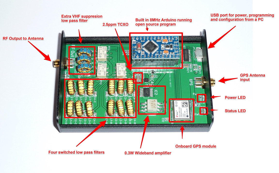
The WSPR Desktop Transmitter is low power transmitter with Arduino firmware that encodes WSPR packets and transmits them using a Silicon Labs Si5351 PLL. The output from the PLL is a square wave that is amplified by a 74AC244 Line driver IC and matched to 50 ohm by a MiniCircuits wide-band transformer.
The Reference clock for the PLL is an Abracon ASTX-H11 TCXO oscillator on 25MHz.
The reference has a 2.5ppm stability specification that ensures good frequency stabilization when transmitting the narrow band WSPR packets.
The signal exits the power amplifier as a square wave and needs to be filtered to remove overtones.
This is done by four switched low pass filters and an extra VHF suppression low pass filter. This takes down the overtones 50dB or more compared to the carrier.
The building blocks of the transmitter. Note: picture shows an older revision with hand wound coils
Operation.
Setting the configuration for the Transmitter.
-
Connect the included GPS antenna to the SMA connector marked "GPS Antenna" and place the GPS puck so that is has visibility of the sky.
-
Connect an HF antenna or dummy load to the SMA connector marked "RF Out".
-
Connect the USB port to PC computer.
-
Download and install the Configuration software from GitHub : https://github.com/HarrydeBug/1011-WSPR-TX_LP1/tree/master/PC%20Software/
-
Start the PC configuration and choose a Serial port from the drop down list.
-
Click the “Connect” button. If the serial port belongs to a WSPR Transmitter then the software will pull data from it and display in the Software.
If you have several serial ports in your PC, you may have to try to connect to each of them in order until you find the right one. -
Set the configuration you want and click the save button.
-
To start the WSPR beacon click the “Start” button in the WSPR Configuration section as shown in the picture.
-
There is also a Signal Generator mode so the WSPR Desktop Transmitter can be used as a piece of test equipment in your shack. It can output a 23dBm sinus wave from 2kHz to 50MHz depending on model. There is a highest frequency that can be used as set by the low pass filter with the highest frequency.
The output power will decline rapidly above the cutoff frequency. -
To stop the WSPR Beacon or the Signal generator click the “stop” button.
-
Save the configuration and operate the transmitter either connected to the computer or standalone with a USB power adapter.
Running the Transmitter standalone.
-
The WSPR Transmitter will either start in WSPR Beacon mode, in Signal generator mode or in idle mode depending on what the start mode is set to in the configuration program, se picture.
If it is set to WSPR Beacon, it will continuously transmit as set in the configuration.
The Yellow status Led will indicate what it is doing at the moment.
Status information from the LEDs
Yellow LED Off= Waiting/Idling
Yellow LED Single blinking=Acquiring position from the GPS Satellites.
Yellow LED Double blinking=Waiting for top of even minute.
Yellow LED fast blinking periodically =Transmitting WSPR Beacon.
Yellow LED On = Signal Generator is running.
Status information in the software.
The status can also be view in the PC software.


Hardware:
The hardware can be divided in to the following blocks:
Powersupply
There are two power supplies in the transmitter, 5V and 3.3V
5V:
The transmitter is powered by an external 5V supply using a micro-USB connector.
The maximum current usage by the transmitter is around 250mA.
5V is only used by the power amplifier.
The 5V is passing true a polyfuse that protects the external power supply in case of a short circuit.
3.3V
Most of the electronics in the transmitter runs on 3.3V that it gets from the voltage regulator VR1.
Micro controller
The micro controller is an Arduino Pro Mini 8MHz 3.3V. It can be accessed and programmed to using the USB port. It will show up as a Serial port.
The Arduino runs the software (sometimes called firmware in the text) that handles all the hardware and encodes the WSPR packets.
The connections to it can be best viewed in the schematics and the software can be replaced by the user.
It comes pre-programmed with a firmware that is open source and can be downloaded from the Github link at the top of the page.
GPS
The GPS is comprises of an on-board GPS Chip and an external active antenna.
GPS module:
The micro controller communicates with the GPS module using a serial port.
The GPS runs on 3.3V just like the micro controller. This voltage is also used to power the GPS active antenna.
GPS Antenna:
A GPS antenna must always be fitted for WSPR operations as the GPS time is needed for accurate timing.
A passive or active antenna can be used, it comes delivered with an active antenna with 3m cable.
The active antenna has a magnet at the base.
RF Oscillator
The RF oscillator is a Silicon Labs Si5351 that is using a TCXO as a frequency reference for the Si5351 PLL.
TCXO:
I have used TCXOs with different frequencies for supply reasons. They are normally either 20,25,26 or 27MHz variants.
The frequency is stamped on the component or alternatively can be measured with a frequency counter on the capacitor C8.
The TCXO has a 1.5ppm stability which is sufficient as long as the temperature fluctuations are not extreme and fast.
The TCXO has internal electronics that tries to keep the output frequency constant when temperature changes affect the internal quartz oscillator.
Even though the TCXO has internal compensation to try to keep the frequency constant the absolute frequency can vary a bit between component.
This offset is often not more than few tens of hertz from true frequency. As this is the reference for the PLL output it will affect the final frequency of the output if not corrected for.
Because of this every TCXO is measured and saved in the EEPROM of the Arduino. Using this information the firmware can use it in the PLL calculation and have the Si5351 PLL output the intended frequency as set by the WSPR routine.
At each WSPR transmission the software will randomly pick a frequency within the 200 Hertz WSPR block and use that frequency for the duration of the 2 minutes. Subsequent transmission will use another random picked frequency.
RF Power Amplifier
Amplification.
The power amplifier is a line driver IC. It raises the voltage from 3.3V to 5V peak-to-peak and has a low output impedance. The output transformer T1 adapts the low impedance to 50ohm and in the process steps up the voltage. The output power from T1 is about 23dBm on most bands (200mW).
PA Bandwith.
The driver IC and stray inductance in the PC board will limit the high frequency response and the output transformer will limit the low frequency range.
We therefore get lower output power on some of the bands at the extreme of the frequency coverage.
Se table below for typical output power on the different bands. There can be some variation on individual transmitters from these values with about a 1 dB +/-.
Software:
The software can be downloaded from my download section or from my Gihub.
The software is for PC running Windows, there is no Linux or Mac software however the API used to communicate with the Arduino is documented and can be found in the Github. Using this information it is possible to write software for other platforms if a user would feel the need to have it outside PC/Windows.